
Trip Indications
Understanding trip codes is an important part of keeping your equipment running smoothly. Below are some of the more common codes you may come across when using your Control Techniques Unidrive M700 series drive:
| Trip | Diagnosis |
|---|---|
| Over Volts | DC bus voltage has exceeded the peak level or maximum continuous level for 15 seconds |
| Trip 2 | The Over Volts trip indicates that the DC bus voltage has exceeded the VM_DC_VOLTAGE[MAX] or VM_DC_VOLTAGE_SET[MAX] for 15 s. The trip threshold varies depending on voltage rating of the drive as shown below  Recommended actions: • Increase deceleration ramp (Pr 00.004) • Decrease the braking resistor value (staying above the minimum value) • Check nominal AC supply level • Check for supply disturbances which could cause the DC bus to rise • Check motor insulation using an insulation tester |
| OI ac | OI ac Instantaneous output over current detected |
| Trip 3 | The instantaneous drive output current has exceeded VM_DRIVE_CURRENT[MAX]. This trip cannot be reset until 10 s after the trip was initiated.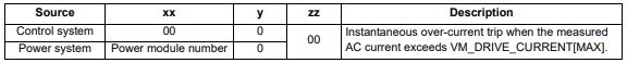 Recommended actions: • Acceleration/deceleration rate is too short • If seen during auto-tune reduce the voltage boost • Check for short circuit on the output cabling • Check integrity of the motor insulation using an insulation tester • Check feedback device wiring • Check feedback device mechanical coupling • Check feedback signals are free from noise • Is motor cable length within limits for the frame size • Reduce the values in the speed loop gain parameters - (Pr 03.010, 03.011, 03.012) or (Pr 03.013, 03.014, 03.015) • Has the phase angle autotune been completed? (RFC-S mode only) • Reduce the values in current loop gain parameters (RFC-A, RFC-S modes only) |
| Inductance | Inductance measurement out of range or motor saturation not detected |
| Trip 8 | This trip occurs in RFC-S mode when the drive has detected that the motor inductances are not suitable for the operation being attempted. The trip is either caused because the ratio or difference between Ld and Lq is too small or because the saturation characteristic of the motor cannot be measured. If the inductance ratio or difference is too small this is because one of the following conditions is true: (No-load Lq (05.072)- Ld (05.024)) / Ld (05.024) < 0.1 (No-load Lq (05.072) - Ld (05.024)) < (K / Full Scale Current Kc (11.061))H where: 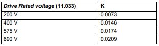 If the saturation characteristic of the motor cannot be measured this is because when the flux in the motor is changed the measured value of Ld does change sufficiently due to saturation to be measured. When half of Rated Current (05.007) is applied in the d axis of the motor in each direction the inductance must fall change at least (K / (2 x Full Scale Current Kc (11.061)). The specific reasons for each of the sub-trips are given in the table below: 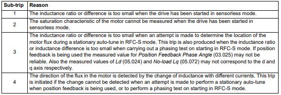 Recommended actions for sub-trip 1: • Ensure that RFC Low Speed Mode (05.064) is set to Non-salient (1), Current (2) or Current No test (3). Recommended actions for sub-trip 2: • Ensure that RFC Low Speed Mode (05.064) is set to Non-salient (1), Current (2) or Current No test (3). Recommended actions for sub-trip 3: • None. The trip acts as a warning. Recommended actions for sub-trip 4: • Stationary autotune is not possible. Perform a minimal movement or rotating autotune. • Phasing test on starting is not possible. Use a position feedback device with commutation signals or absolute position |
| Motor Too Hot | Output current overload timed out (I2t) |
| Trip 20 | The Motor Too Hot trip indicates a motor thermal overload based on the Rated Current (Pr 05.007) and Motor Thermal Time Constant (Pr 04.015). Pr 04.019 displays the motor temperature as a percentage of the maximum value. The drive will trip on Motor Too Hot when Pr 04.019 gets to 100 %. Recommended actions: • Ensure the load is not jammed / sticking • Check the load on the motor has not changed • If seen during an auto-tune test in RFC-S mode, ensure the motor Rated Current in Pr 05.007 is ≤ Heavy duty current rating of the drive • Tune the Rated Speed (Pr 05.008) (RFC-A mode only) • Check feedback signal for noise • Ensure the motor rated current is not zero • This trip can be disabled and current limiting activated on the motor overload by setting thermal protection mode Pr 04.016 to 1. |
| OHt Power | Power stage over temperature |
| Trip 22 | This trip indicates that a power stage over-temperature has been detected. From the sub-trip ‘xxyzz’, the Thermistor location which is indicating the over-temperature is identified by ‘zz’.The thermistor numbering is different for a single module type drive (i.e. no parallel board fitted) and a multi-module type drive (i.e. parallel board fitted with one or more power modules) as shown below: Single module type drive: 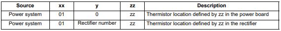 Multi-module type system: 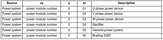 Note that the power module that has caused the trip cannot be identified except for the braking IGBT temperature measurement Recommended actions: • Check enclosure / drive fans are still functioning correctly • Force the heatsink fans to run at maximum speed • Check enclosure ventilation paths • Check enclosure door filters • Increase ventilation • Reduce the drive switching frequency • Reduce duty cycle • Increase acceleration / deceleration rates • Use S ramp (Pr 02.006) • Reduce motor load • Check the derating tables and confirm the drive is correctly sized for the application. • Use a drive with larger current / power rating |
| An Input 1 Loss | Analog input 1 current loss (Unidrive M700 / M701) |
| Trip 28 | An Input 1 Loss trip indicates that a current loss was detected in current mode on Analog input 1 (Terminal 5, 6). In 4-20 mA and 20-4 mA modes loss of input is detected if the current falls below 3 mA. Recommended actions: • Check control wiring is correct • Check control wiring is undamaged • Check the Analog Input 1 Mode (07.007) • Current signal is present and greater than 3 mA |
| Phase Loss | Supply phase loss |
| Trip 32 | The Phase Loss trip indicates that the drive has detected an input phase loss or large supply imbalance. Phase loss can be detected directly from the supply where the drive has a thyristor base charge system (Frame size 8 and above). If phase loss is detected using this method the drive trips immediately and the xx part of the sub-trip is set to 01. In all sizes of drive phase loss is also detected by monitoring the ripple in the DC bus voltage in which case the drive attempts to stop the drive before tripping unless bit 2 of Action On Trip Detection (10.037) is set to one. When phase loss is detected by monitoring the ripple in the DC bus voltage the xx part of the sub-trip is zero.  (1) Input phase loss detection can be disabled when the drive required to operate from the DC supply or from a single phase supply in Input Phase Loss Detection Mode (06.047). (2) For a parallel power-module system the rectifier number will be one as it is not possible to determine which rectifier has detected the fault. This trip does not occur in regen mode. Recommended actions: • Check the AC supply voltage balance and level at full load • Check the DC bus ripple level with an isolated oscilloscope • Check the output current stability • Check for mechanical resonance with the load • Reduce the duty cycle • Reduce the motor load • Disable the phase loss detection, set Pr 06.047 to 2. |
| Out Phase Loss | Output phase loss detected |
| Trip 98 | The Out Phase Loss trip indicates that phase loss has been detected at the drive output. 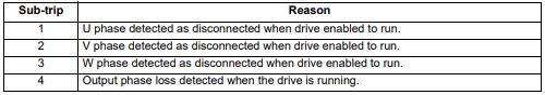 NOTE: If Pr 05.042 = 1 the physical output phases are reversed, and so sub-trip 3 refers to physical output phase V and sub-trip 2 refers to physical output phase W. Recommended actions: • Check motor and drive connections • To disable the trip set Output Phase Loss Detection Enable (06.059) = 0 |
| OI dc | Power module over current detected from IGBT on state voltage monitoring |
| Trip 109 | The OI dc trip indicates that the short circuit protection for the drive output stage has been activated. The table below shows where the trip has been detected. This trip cannot be reset until 10 s after the trip was initiated. 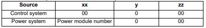 Recommended actions: • Disconnect the motor cable at the drive end and check the motor and cable insulation with an insulation tester • Replace the drive |
| Configuration | The number of power modules installed is different from the modules expected |
| Trip 111 | The Configuration trip indicates that the Number Of Power Modules Detected (11.071) does not match the previous value stored. The sub-trip value indicates the number of power modules expected. Recommended actions: • Ensure that all the power modules are correctly connected • Ensure all the power modules have powered up correctly • Ensure that the value in Pr 11.071 is set to the number of power modules connected • Set Pr 11.035 to 0 to disable the trip if it is not required This trip is also initiated if the number of external rectifiers connected to each power module is less than the number defined by Number Of Rectifiers Expected (11.096). If this is the reason for the trip the sub-trip is 10x where x is the number of external rectifiers that should be connected. Recommended actions: • Ensure that all the external rectifiers are connected correctly • Ensure that the value in Number Of Rectifiers Expected (11.096) is correct |
Alarm Indications
In any mode, an alarm is an indication given on the display by alternating the alarm string with the drive status string on the first row and showing the alarm symbol in the last character in the first row. If an action is not taken to eliminate any alarm except "Auto Tune and Limit Switch" the drive may eventually trip. Alarms are not displayed when a parameter is being edited, but the user will still see the alarm character on the upper row.
| Alarm string | Description |
|---|---|
| Brake Resistor | Brake resistor overload. Braking Resistor Thermal Accumulator (10.039) in the drive has reached 75.0 % of the value at which the drive will trip. |
| Motor Overload | Motor Protection Accumulator (04.019) in the drive has reached 75.0 % of the value at which the drive will trip and the load on the drive is >100 %. |
| Ind Overload | Regen inductor overload. Inductor Protection Accumulator (04.019) in the drive has reached 75.0 % of the value at which the drive will trip and the load on the drive is >100 %. |
| Drive Overload | Drive over temperature. Percentage Of Drive Thermal Trip Level (07.036) in the drive is greater than 90 %. |
| Auto Tune | The autotune procedure has been initialized and an autotune in progress. |
| Limit Switch | Limit switch active. Indicates that a limit switch is active and that is causing the motor to be stopped. |
Status Indications
| Upper row string | Description | Drive output stage |
|---|---|---|
| Inhibit | The drive is inhibited and cannot be run. The Safe Torque Off signal is not applied to Safe Torque Off terminals or Pr 06.015 is set to 0 | Disabled |
| Ready | The drive is ready to run. The drive enable is active, but the drive inverter is not active because the final drive run is not active | Disabled |
| Stop | The drive is stopped / holding zero speed. | Enabled |
| Run | The drive is active and running | Enabled |
| Scan | The drive is enabled in Regen mode and is trying to synchronize to the supply | Enabled |
| Supply Loss | Supply loss condition has been detected | Enabled |
| Deceleration | The motor is being decelerated to zero speed / frequency because the final drive run has been deactivated. | Enabled |
| dc injection | The drive is applying dc injection braking | Enabled |
| Position | Positioning / position control is active during an orientation stop | Enabled |
| Trip | The drive has tripped and no longer controlling the motor. The trip code appears in the lower display | Disabled |
| Active | The regen unit is enabled and synchronized to the supply | Enabled |
| Under Voltage | The drive is in the under voltage state either in low voltage or high voltage mode | Disabled |
| Heat | The motor pre-heat function is active | Enabled |
| Phasing | The drive is performing a ‘phasing test on enable’ | Enabled |
Option module and NV Media Card and other status indications at power-up
| First row string | Second row string | Status |
|---|---|---|
| Booting | Parameters | Parameters are being loaded |
| Drive parameters are being loaded from a NV Media Card | ||
| Booting | User Program | User program being loaded |
| User program is being loaded from a NV Media Card to the drive | ||
| Booting | Option Program | User program being loaded |
| User program is being loaded from a NV Media Card to the option module in slot X | ||
| Writing To | NV Card | Data being written to NV Media Card |
| Data is being written to a NV Media Card to ensure that its copy of the drive parameters is correct because the drive is in Auto or Boot mode | ||
| Waiting For | Power System | Waiting for power stage |
| The drive is waiting for the processor in the power stage to respond after power-up | ||
| Waiting For | Options | Waiting for an option module |
| The drive is waiting for the Options Modules to respond after power-up |
||
| Uploading From | Options | Loading parameter database |
| At power-up it may be necessary to update the parameter database held by the drive because an option module has changed or because an applications module has requested changes to the parameter structure. This may involve data transfer between the drive an option modules. During this period ‘Uploading From Options’ is displayed | ||
Programming error indications
Following are the error message displayed on the drive keypad when an error occurs during programming of drive firmware.
| Error String | Reason | Solution |
|---|---|---|
| Error 1 | There is not enough drive memory requested by all the option modules. | Power down drive and remove some of the option modules until the message disappears. |
| Error 2 | At least one option module did not acknowledge the reset request. | Power cycle drive |
| Error 3 | The boot loader failed to erase the processor flash | Power cycle drive and try again. If problem persists, return drive |
| Error 4 | The boot loader failed to program the processor flash | Power cycle drive and try again. If problem persists, return drive |
| Error 5 | One option module did not initialize correctly. Option module did not set Ready to Run flag. | Remove faulty option module |
Need further help?
If you have an AC / DC drive module breakdown or stability issue our engineers are able to analyse the whole machine to identify where the control issues lie. Our extensive experience in retrofit and new projects means we have the knowledge to look deep into the control system where we commonly find the peripheral devices are faulty rather than the drive module.
Telephone support
Where appropriate we are often able to offer technical support by phone, we will need the following information from you:
- Your official Purchase order (this must be received prior to any support).
- Details of the Drive.
- Error Codes.
- We may also need copies of drawings and software to aid diagnosis.
Telephone support rates are £100.00 per hour, with a minimum charge of 1 hour.
Our team of engineers are also able to offer on site service and breakdown support throughout the UK to get you up and running again quickly, please enquire for details.